Projects
A collection of projects that I have undertaken for school, research, or personal applications.
Simulated Unmanned Ground Vehicle (UGV)
While assisting with research in the Aerospace Systems Laboratory at UT Arlington, I became particularly interested in the master’s thesis of a fellow student, where 3D object detection and machine learning algorithms would be implemented on one of the lab’s rover-like ground vehicles to have it navigate autonomously in a given environment. While the algorithms seemed to be in good working order, issues often arose with faulty batteries or motors, tedious sensor calibrations, and many other setbacks that often plague real-world testing. This in turn slows down the testing process and even distorts the results of these tests, since it is often not clear whether the fault lies with the algorithms or with the physical hardware.
This project is a potential solution to that problem. Utilizing the Robot Operating System (ROS), I have developed a package that simulates an entire ground vehicle within the Gazebo simulation environment. This ground vehicle is identical to the vehicle used in the lab, and the same sensors on the real vehicle – namely a camera and LIDAR sensor – will also be simulated within this environment to feed the algorithms the necessary sensory inputs needed to properly direct the vehicle within the given environment. The advantages of such a simulation include faster testing cycles that allow for more tests to be done within a certain time frame as well as a lack of interference due to hardware problems; any issues found within the simulation can only be attributed to a software issue, which helps to speed up the debugging process.
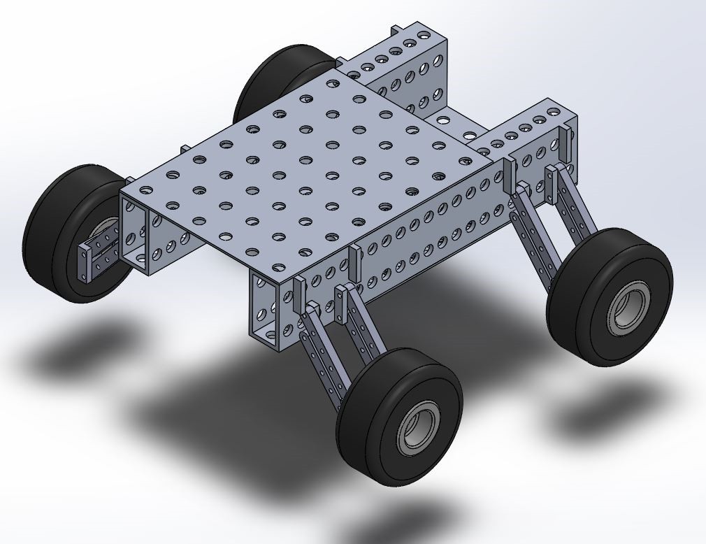
The image above shows a 3D CAD model of the lab’s ground vehicle assembled in SolidWorks. This model was converted into a mesh that was then used in a URDF file by using the “SolidWorks to URDF Exporter” plugin downloaded from the ROS.org website. This plugin essentially converts the SolidWorks model into a ROS package with various links, joints, visual properties, and collision properties being determined within the URDF file in the package. Various adjustments were made to the exported URDF file to account for certain orientation and placement errors made during the exporting process. The collision dimensions were also simplified to minimize computation time for the simulation, thereby reducing lag time when velocity commands were given to the vehicle.
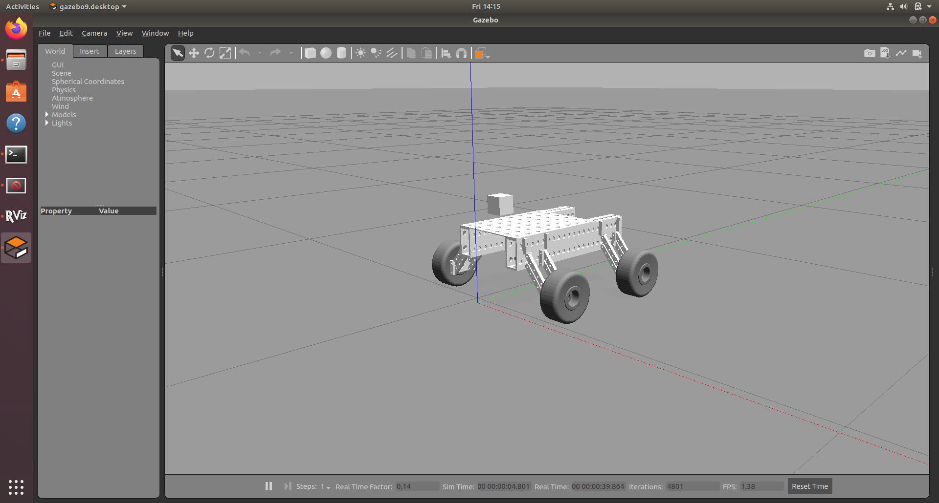
Various other items had to be added to the package for the simulation to run smoothly, including a Gazebo plugin, transmission sections to the URDF file (to allow for movement), controller plugins (for velocity inputs to be possible), and several nodes for controller integrations and state publishing. The camera sensor was also added to the simulation by adding the necessary sensor sections and plugins to the URDF file. The shape of the camera is a basic cube due to a limited need for aesthetics in preliminary simulations, however that can always be changed later. The LIDAR sensor must still be added to the simulated vehicle, once the calibration of the camera sensor is completed (which is currently underway).
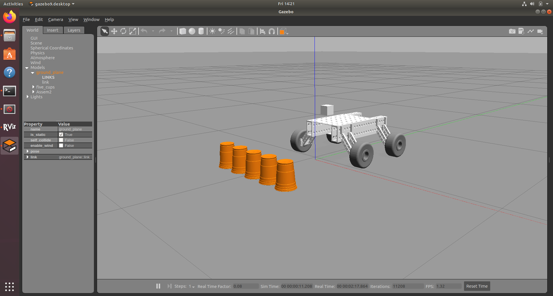
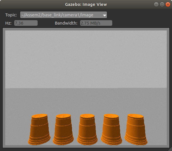
Several orange cups were also placed in front of the vehicle to test if the camera was indeed working and to run sensor calibrations before testing the algorithms. These cups were independently modeled and added as part of the .world file initiated by the launch file within the ROS package. The camera sensor captures images of these cups at a set rate and saves these images for calibration and machine learning processes. One of these captured images is shown below.
There are several improvements that must still be made to this simulation, but the vehicle can be successfully driven and steered at specific velocities. The camera sensor feeds images for calibration and processing, and once the LIDAR sensor is added to the simulation, all this sensor data can be fused and processed to drive the vehicle where it needs to go.
Obstacle Avoidance Testing Platform (Senior Design)
For my undergraduate Senior Design class, I am currently part of a team tasked with the design – and prototyping of any mechanical device or machine that addresses a real-world problem and displays our engineering abilities. We were given the freedom to choose our own projects, and my team and I decided to design a stair-climbing robot that would be capable of carrying a load of up to 35 pounds up a standard flight of stairs in an autonomous manner. The project is mainly aimed at assisting the elderly or those with physical disabilities who are unable to carry heavy loads to their designated rooms or apartments, yet there are many more applications for a robot such as this.
I am the Electronics lead for this project, thereby making me responsible for power distribution, electronics hardware, programming, and testing of all hardware and software on the robot. While the design of our platform was still ongoing, several of our components were being tested on a miniature treaded platform that was purchased online. The testing platform had to be affordable, easy to assemble, and have the same treaded, DC-motor configuration as that of our final platform. These tests are being conducted to ensure that our hardware components are in good working order and that our testing program is bug-less and easily transferable to our final robotic platform.
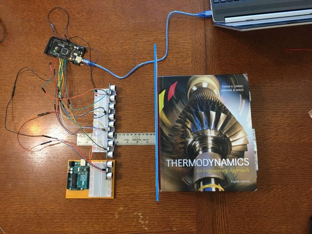
Before the sensors and components could be assembled onto the testing platform, each component had to be individually tested to confirm that they function properly. The image below shows one of the preliminary tests conducted with the sonar sensors. All five sensors were connected to the micro-controller and an obstacle – in this case a large textbook – was placed at a known distance away from the sensors. The microcontroller was programmed to receive the respective pulses sent by each sensor, process those pulses into distance values, and then output those distances onto the serial monitor of a development environment implemented on a laptop.
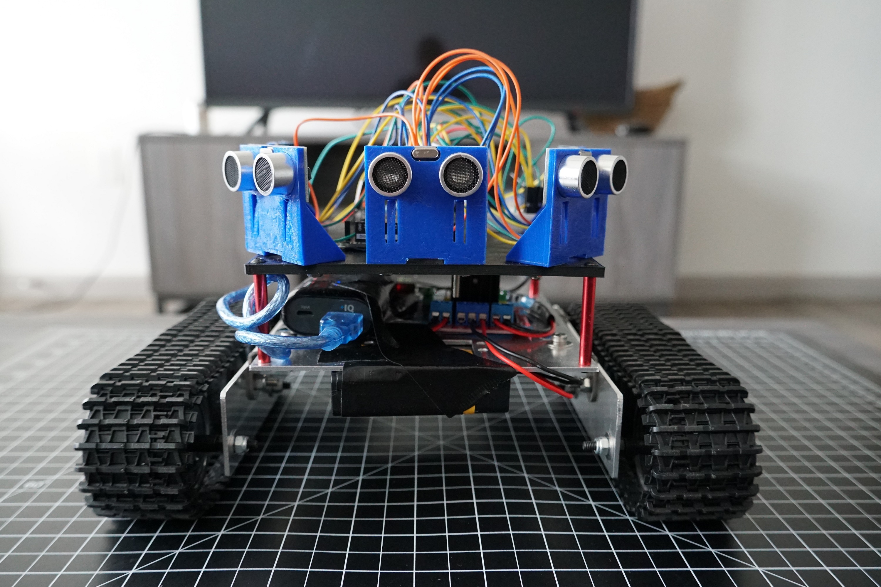
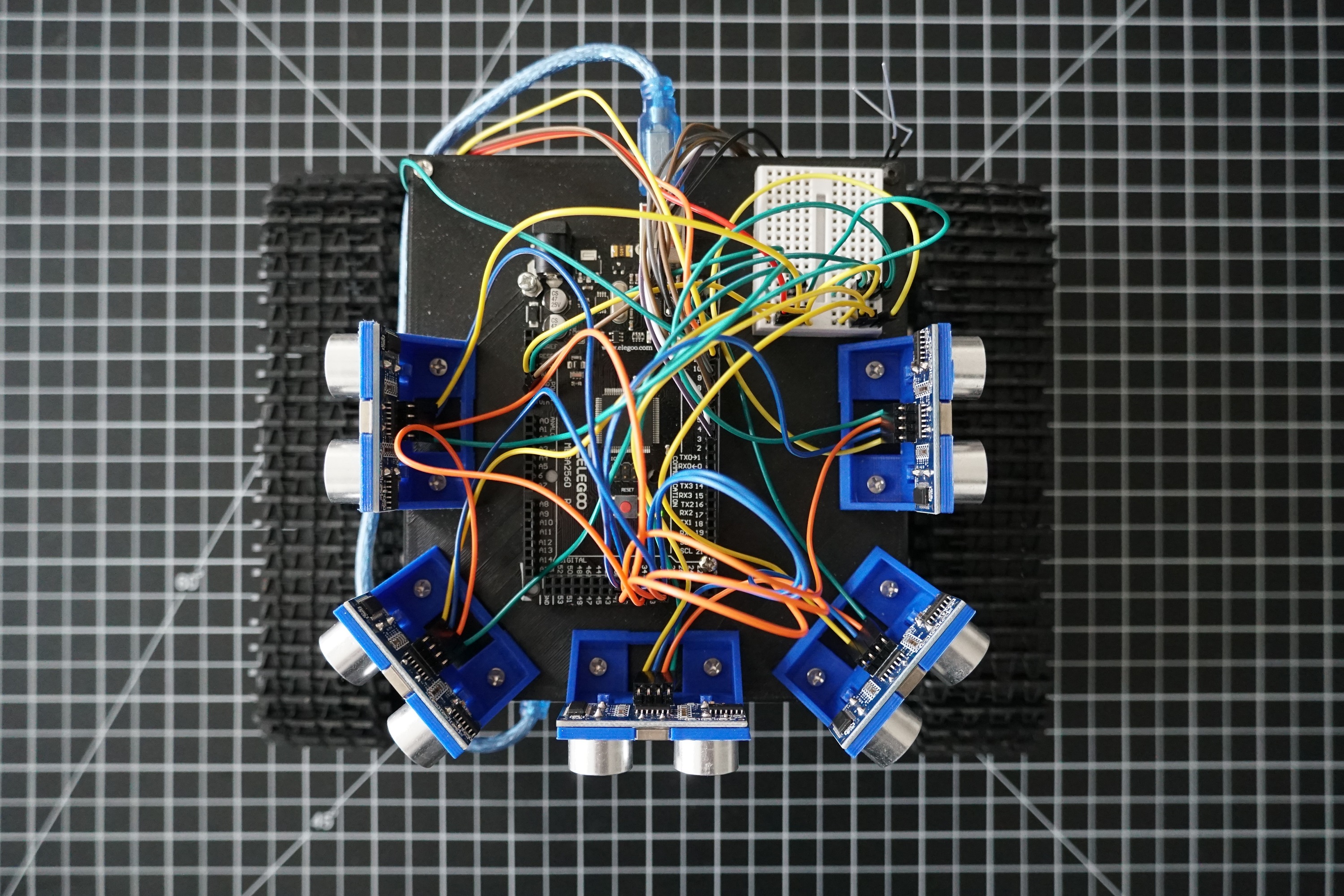
Once the components were individually tested, they were all assembled onto the testing platform shown below. The lithium polymer battery system that would be used on the final platform would be too powerful and heavy for the testing platform, so eight nickel metal hydride (Ni-MH) batteries were placed inside a battery holder case and strapped to the bottom of the platform to provide power to the motors. This was a more affordable option for our testing needs. The sensors were arrayed in 45° increments to give the platform a wide range of distance-sensing capabilities, and once all the components were properly wired and powered, the process of programming the microcontroller and debugging the code could commence.
A receiver was also placed on the platform so that it could be controlled using an Fr-Sky transmitter. Frequent testing of the platform was undertaken to determine how certain changes to the program on the microcontroller would affect the performance of the platform. The formation of code for a Manual mode setting was the first set of code integrated onto the platform. Once the platform was able to consistently move forward or backward at variable speeds, turn, and even pivot on the same spot, the testing shifted to an Automatic mode setting. This mode essentially activates an obstacle-avoidance algorithm that maintains a set speed for the robot and adjusts the velocity of one or both motors when any obstacles (walls, humans, etc.) are within a certain proximity of the robot. A switch on the transmitter was configured to alternate between Manual mode and Autonomous mode as certain situations would require a manual override for practical or safety reasons.
This testing platform is fully operational and – when in Autonomous mode – moves forward at a set speed and adjusts when needed to avoid collisions with surrounding obstacles in its environment. The importance of testing hardware was revealed through trial and error, and the integration of hardware and software needed for this platform to function properly was certainly the most interesting aspect of this project.
The code implemented on the Elegoo micro-controller can be found on Github: